Dvi D To Vga Pinout Diagram
DVI pinout diagram This AV connector pinout diagram example was redesigned from the file: DVI pinout.svg. [en.wikipedia.org/ wiki/ File:DVI_ pinout.svg] "In electronics, a pinout (sometimes written "pin-out") is a cross-reference between the contacts, or pins, of an electrical connector or electronic component, and their functions..

Dvi Pinout PDF
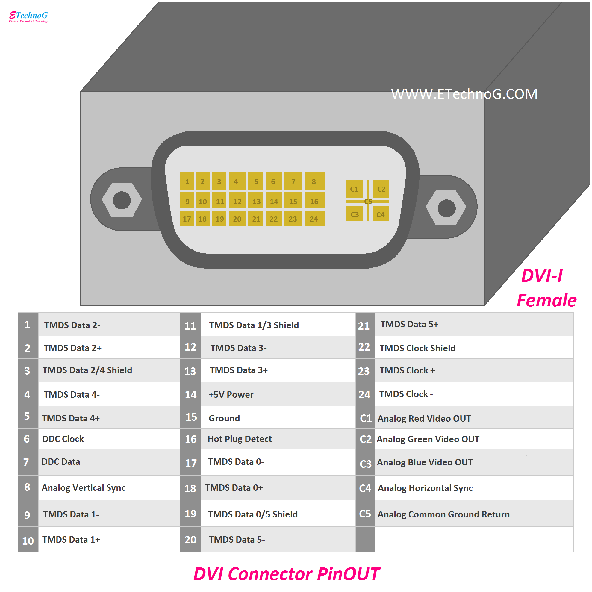
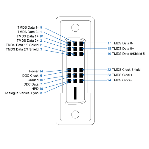
The connector diagram and pin-out table show a DVI-I Digital and Analog [RGB]; 29 pins [modified D style] connector. A DVI-D Digital only connector with 24 pins [modified D style] looks about the same with out the 4 analog 'C' pins. The DVI interface is found on a number of devices including TVs, Computers, Monitors, and Video cards.
VGA, DVI, and HDMI Connector Pinout Diagram ETechnoG
DVI Wiring Information and Pinout Table. Leads Direct is proud to have been an early provider of high quality DVI monitor leads and cables long before some other suppliers in the UK. The company carries a wide range of ready made DVI leads and accessories up to 10m in length at the time of writing, and the range is likely to increase over time.
VGA, DVI, and HDMI Connector Pinout Diagram ETechnoG
What is the DVI Pinout Diagram? The DVI pinout is a list of all the pins that are on a DVI-D connector. Some versions of the connector have extra pins or notches in each position, so it is, therefore, necessary to know this information in order to be able to figure out what is what.
16 Types of Computer Ports and Their Functions
Most digital monitors have a DVI-D connector, while monitors which support both digital and analog signals usually have a DVI-D and VGA connector. Note that female DVI-D connectors will not accept male DVI-A or DVI-I cables as those connectors have the additional 4 analog pins that DVI-D lacks. DVI-I single-link connectors have 23 pins (18+5.
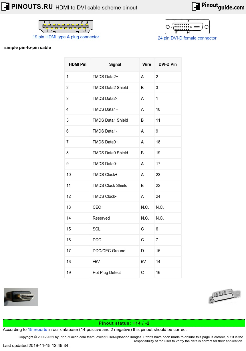
HDMI to DVI cable scheme pinout diagram
Wikipedia] The example "DVI pinout diagram" was created using the ConceptDraw PRO diagramming and vector drawing software extended with the Audio and Video Connectors solution from the Engineering area of ConceptDraw Solution Park. Used Solutions Engineering > Audio and Video Connectors Electrical Symbols — Terminals and Connectors

Mini Dvi Wiring Diagram
"Pinout" is a term describing how an electrical cable is wired. Some cables do not have pinouts because they only contain a single internal wire, like coax cables. But if a cable has multiple pins on the end of the cable, it will have a pinout. Each type of multi-pin cable has a standard pinout or two, but these layouts are not set in stone.
Understanding DVI Connectors
The example "DVI pinout diagram" was created using the ConceptDraw PRO diagramming and vector drawing software extended with the Audio and Video Connectors solution from the Engineering area of ConceptDraw Solution Park. A female DVI-I socket from the front. Used Solutions.
dvi connector for wiring diagram
DVI pinout diagram This AV connector pinout diagram example was redesigned from the Wikipedia file: DVI Connector Types.svg. [en.wikipedia.org/ wiki/ File:DVI_ Connector_ Types.svg] "Digital Visual Interface (DVI) is a video display interface developed by the Digital Display Working Group (DDWG).

Dremel Junkie 17" DVI Pinout Confirmed
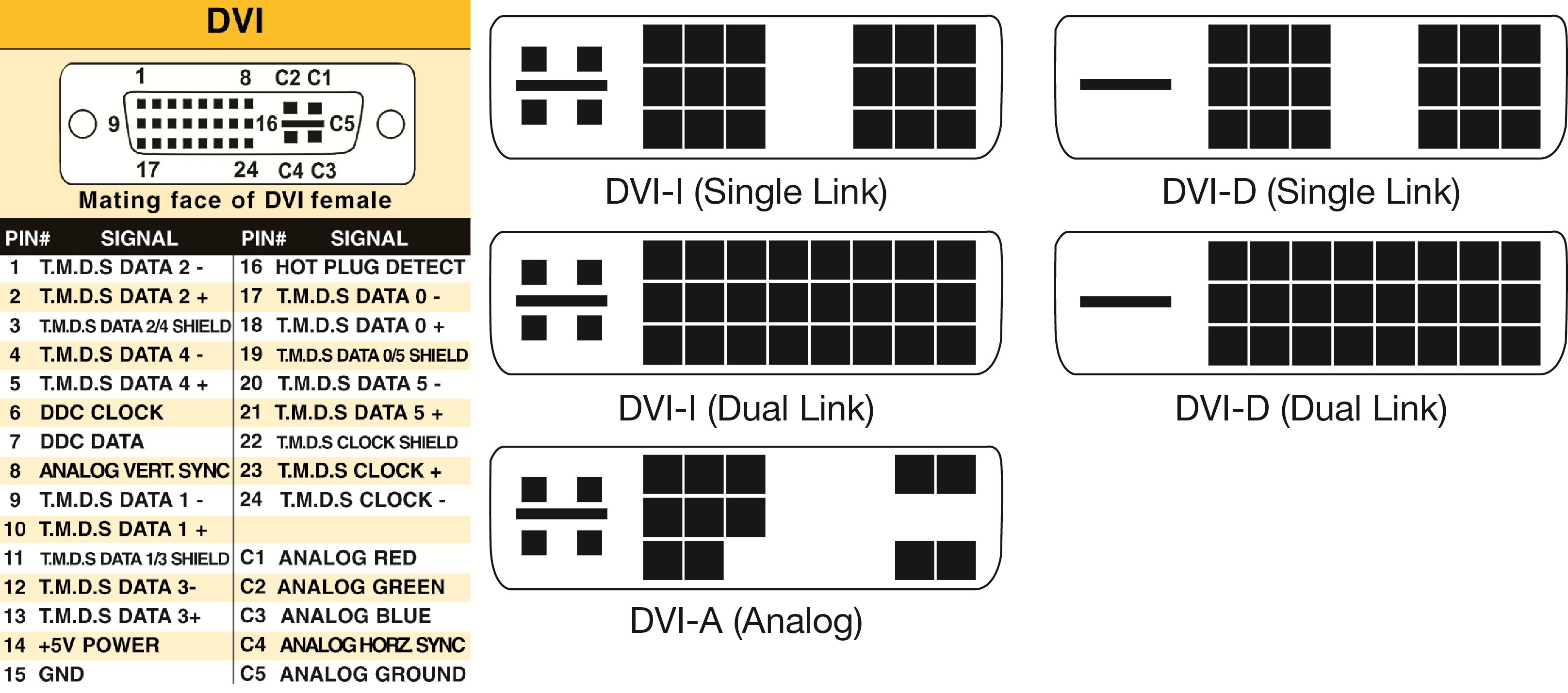
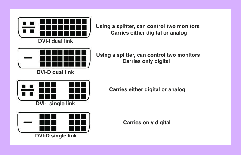
The connector diagrams for the DVI-D, DVI-A and DVI-I connectors for dual link and single link are shown in the following figure. Fig. 3: Diagram for DVI standard connectors DVI connectors are commonly found in devices with flat panel display like television with LCD screen, plasma screen etc.
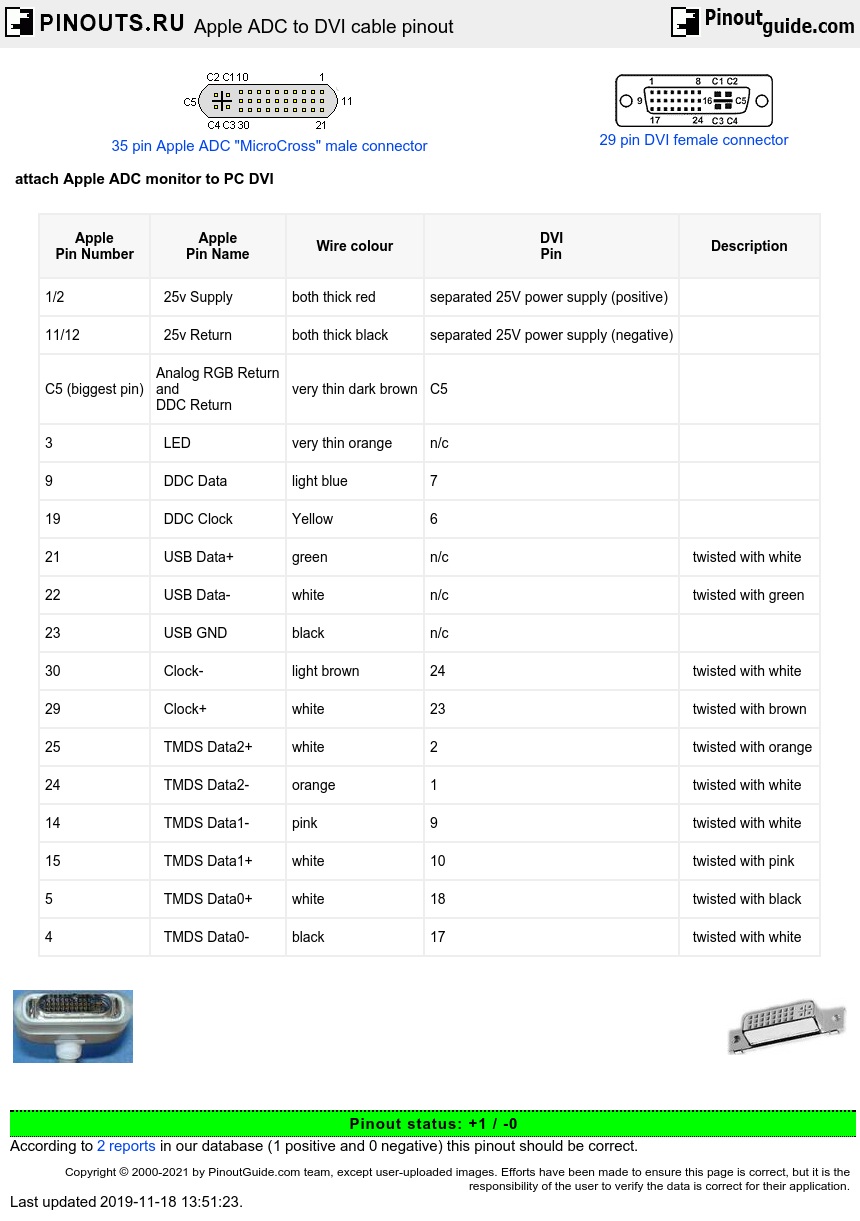
Apple ADC to DVI cable pinout diagram
DVI pinout diagram This pinout diagram example showing a VGA connector (as viewed from the socket) was redesigned from the Wikimedia Commons file: DE15 Connector Pinout.svg. [commons.wikimedia.org/ wiki/ File:DE15_ Connector_ Pinout.svg] "A Video Graphics Array (VGA) connector is a three-row 15-pin DE-15 connector.

DVI Pinout Diagram
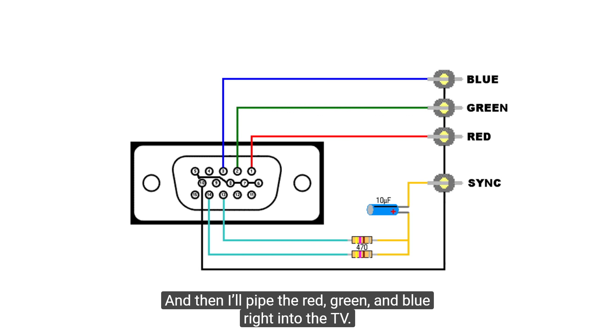
Edit Submit New Most computer graphics cards nowadays does not have a Video Graphics Array connector. Some of them outputs the RGBHV (used in VGA) through their Digital Video Interface. If a graphics card has a DVI-I connector, but no VGA connector, it is likely to output VGA through DVI-I.
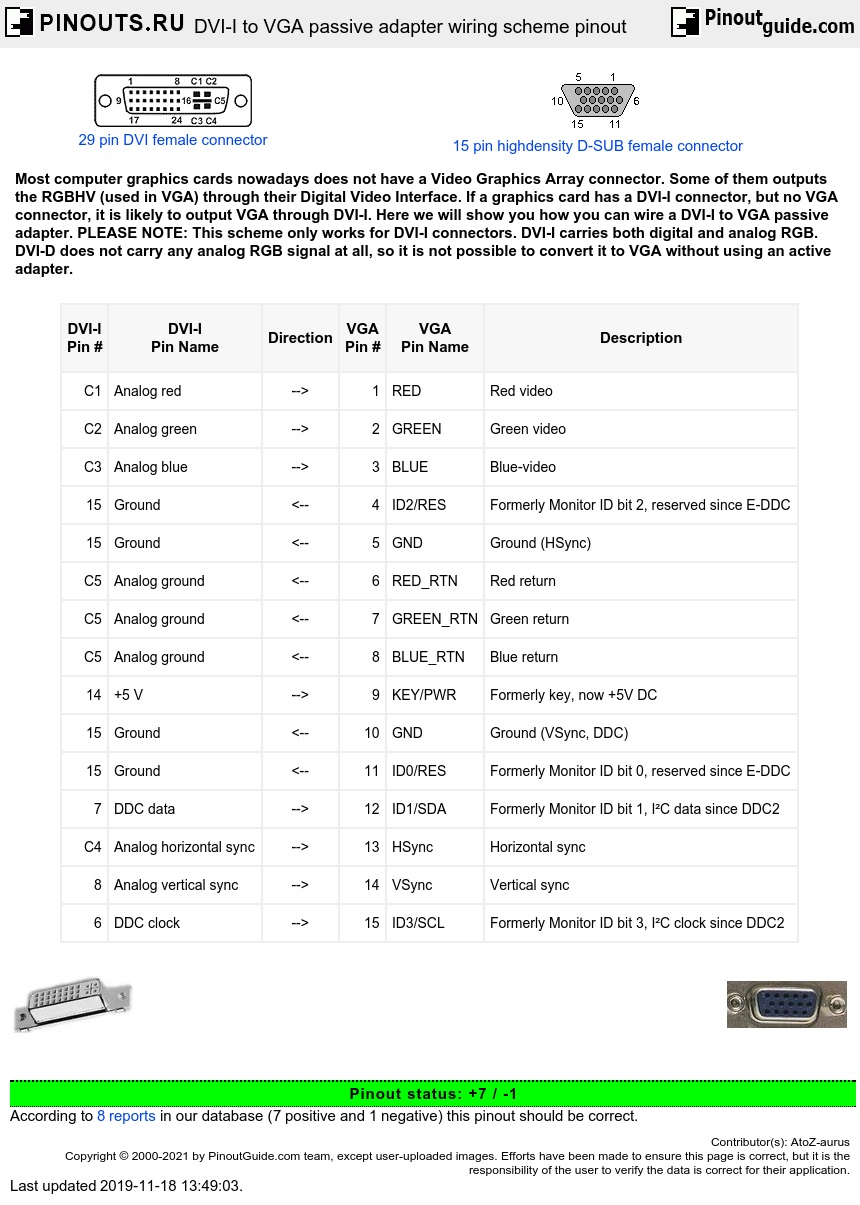
DVII to VGA passive adapter wiring scheme pinout diagram
Digital Visual Interface ( DVI) is a video display interface developed by the Digital Display Working Group (DDWG). The digital interface is used to connect a video source, such as a video display controller, to a display device, such as a computer monitor.

Dvi Pinout Wiring
VGA pins 5,10 are general ground and sync ground and should be connected to DVI-15. At least, that's how it was on my broken adapter. Note that the RGB operating voltages are different than the TTL signaling voltages on the other lines, so keeping the two grounds separate might be wise.
Dvii Pinout Diagram
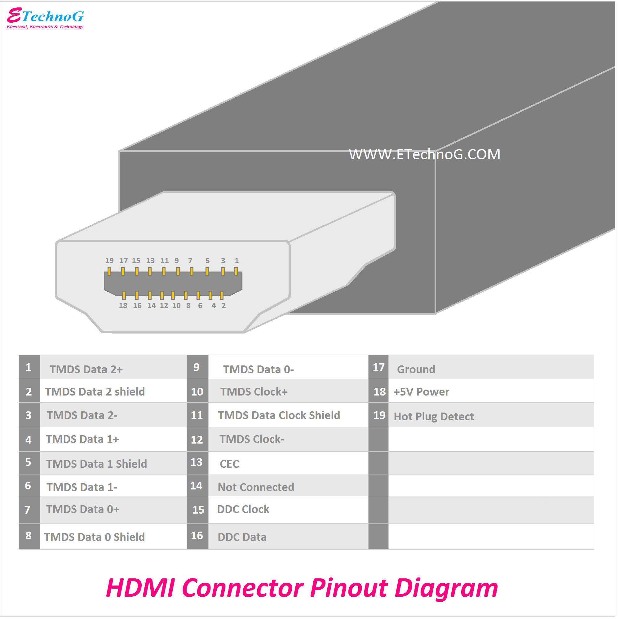
Comment Edit Submit New simple pin-to-pin cable HDMI supports standard, enhanced, or high-definition video, plus multi-channel digital audio on a single cable. This video data is then encoded into TMDS for transmission digitally over HDMI. HDMI also includes support for 8-channel uncompressed digital audio.
bnc dvi wiring
You can see in pin diagram the DVI-I pins are a combination of both DVI-A and DVI-D. DVI-I (Single Link) supports a video stream at 1920X1200 @ 60 Hz. DVI-I (Dual Link) support a video stream at 2560X1600 @ 60 Hz. DVI Connector Pin Details and Configuration The function of each pin in DVI-I port is stated below.